Drones design
2024-06-27 16:37:56
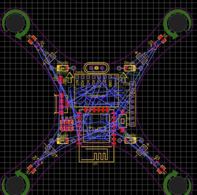 Create basic drone shapes using lines and circles (ensuring units are in millimeters). In addition, symmetrical lines have been added to place components in a perfectly balanced manner, thereby reducing the complexity of the drone algorithm and making it stable. Add curved edges to make it more durable. The size of the drone is determined based on the propeller, and there are wide dimensions to choose from (40mm, 55mm, 65mm), which will be most suitable for the 8520 motor.
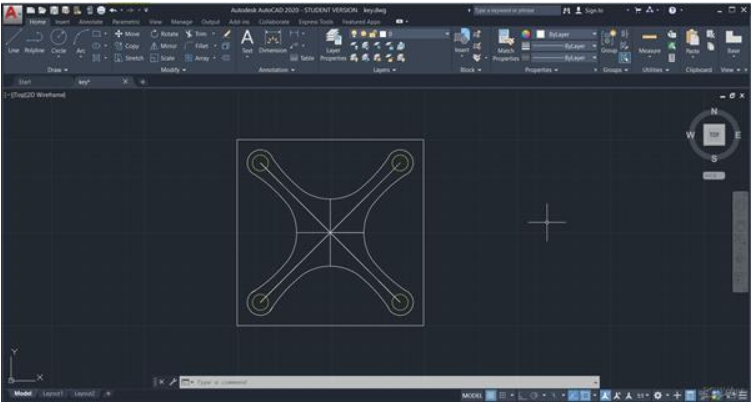
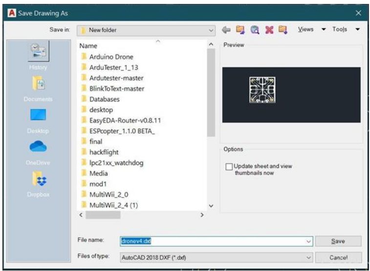
After the design is completed, add an outer square of 10x10 centimeters and save the chart in. dxf format.
EASYEDA's circuit design:
Start designing circuits in EASYEDA now.
Create a new project and draw a schematic.
Use network ports to make the schematic look clean and tidy

After the schematic is completed, click "Design" ->Convert the schematic to PCB.
Allow DRC inspection to verify the schematic.
Ensure there are no errors or warnings.
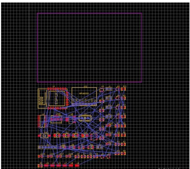
Import dxf file into EASYEDA:
After creating the PCB, we can now import the charts from AutoCAD.
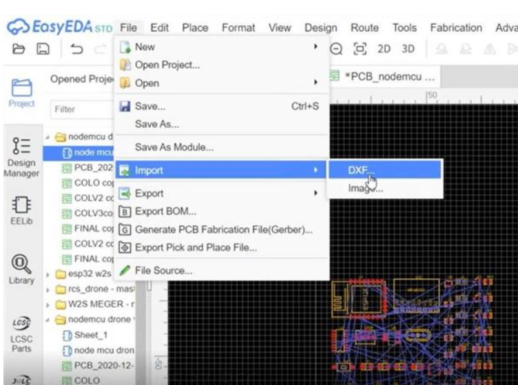
- Make sure to select the layer type as "board outline" and select "stroke width" as 0.245 millimeters
Enable the Convert Circle to HOLE checkbox on the BoardOutLine layer, which will create holes for motor installation.
Start arranging the components as symmetrically as possible.
Keeping the MOSFET near the motor will cool the MOSFET from an extreme state during propeller airflow flight.
Try to keep the IMU in the center position as much as possible, which will stabilize the drone and reduce the complexity of the algorithm.
Adding silk screen arrow markings representing the front of the drone would be helpful during flight.
Add a circular arrow mark indicating the rotation of the motor, which will be helpful when fixing the motor. 
- Use 2D or 3D view functionality to view the final PCB.
Adding all terminal markings is silk screen printing to prevent accidental reverse polarity connections
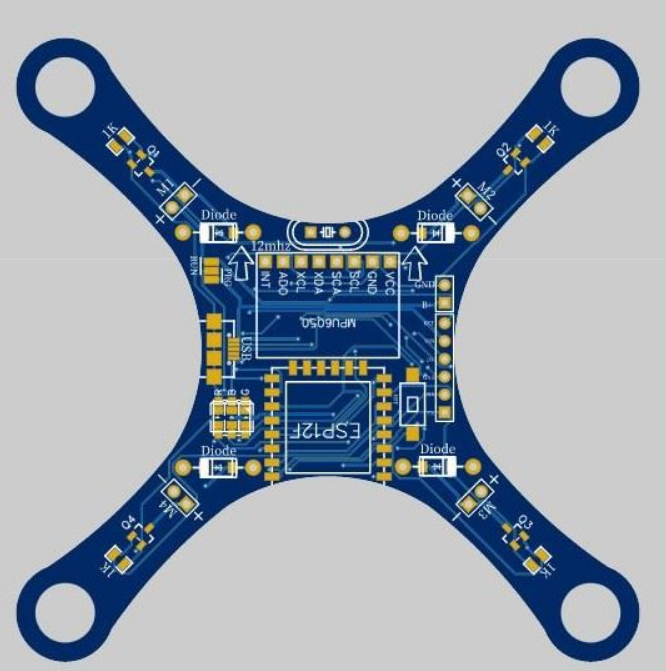
Once satisfied with the final view, export the gerber file (File ->Generate PCB Fabric File (Gerber)
Provide YES for DRC inspection, which will ensure that the PCB design is error free.
Now upload the gerber file to PCBWay and select a thickness of 1.2mm.
I have tested the thickness of the PCB, such as 1mm, 1.2mm, 1.6mm.
1.6mm is more standard, but it adds some weight to the drone. 1mm and less add more flexibility to the drone, making it useless. 1.2mm is the best choice, providing less flexibility, lighter weight, and good frame strength.
During on-site testing, the drone experienced many collisions, and the 1.2mm PCB survived with only some scratches around the drone's arms.


